
SDC-400 diode driver
Product details
Applications
- Diode pumping of DPSS such as Nd:YAG
Features
- Output diode current – up to 400 A, 500 V, 300 us (but 1500 W max)
- Pulse width – 50-300 us
- Repetition rate – up to 500 Hz
- Rise time – < 20-30 us typically
- Modifications are possible
Downloads: Downloads
| File | Size | Updated |
|---|---|---|
| sdc-400-hv-a-step.zip | 26 MB | August 17, 2026 |
| sdc-400-hv-w-step.zip | 21 MB | August 17, 2026 |
| sdc-400-lv-a-step.zip | 24 MB | August 17, 2026 |
| sdc-400-lv-w-step.zip | 19 MB | August 17, 2026 |
| sdc-400-manual-en.pdf | 2 MB | August 17, 2026 |
Product Description
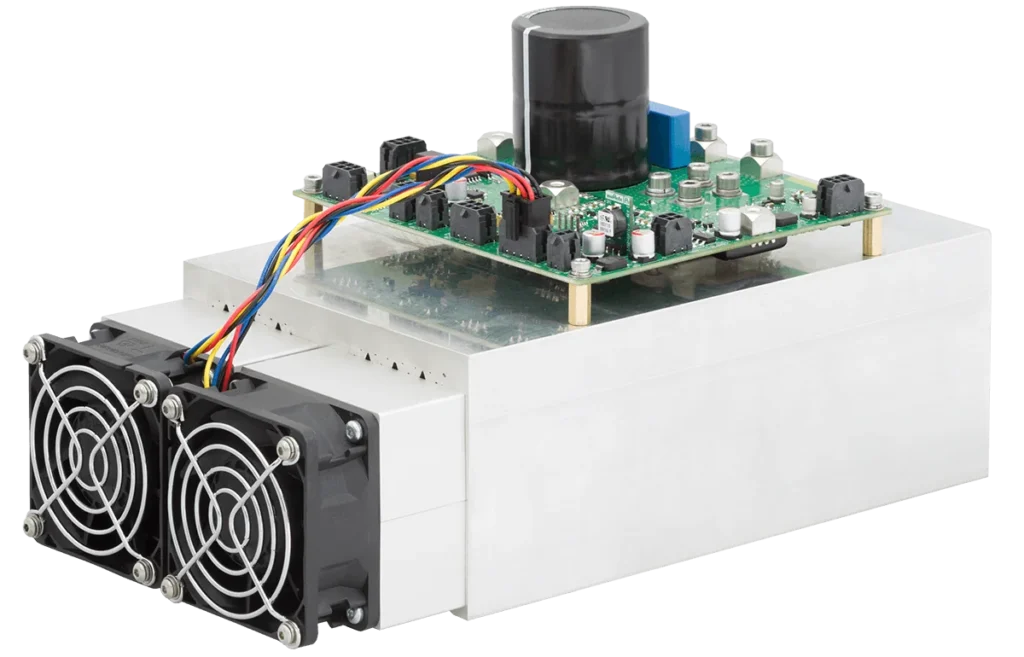
The 1500W SDC-400 diode driver series is an advanced family of open-frame pulsed drivers specifically engineered to power high-power diode-pumped solid-state (DPSS) lasers, including Nd:YAG systems. Designed for demanding applications, this module supplies a precise 50 to 300 µs pulsed current to efficiently drive pumping diodes, capable of delivering up to 1500 W of average power. It offers highly flexible pulse repetition rates, reaching up to 500 Hz for relatively low-voltage setups and 50 Hz for high-voltage configurations.
Designed for maximum integration flexibility, the unit is supplied exclusively as an OEM module, containing only the core diode driver. To complete the system architecture, all ancillary components—including the AC/DC power supply, capacitor bank (if required), and graphical user interface (GUI)—must be provisioned separately. These components can be sourced directly through OEM Tech or via qualified third-party suppliers.
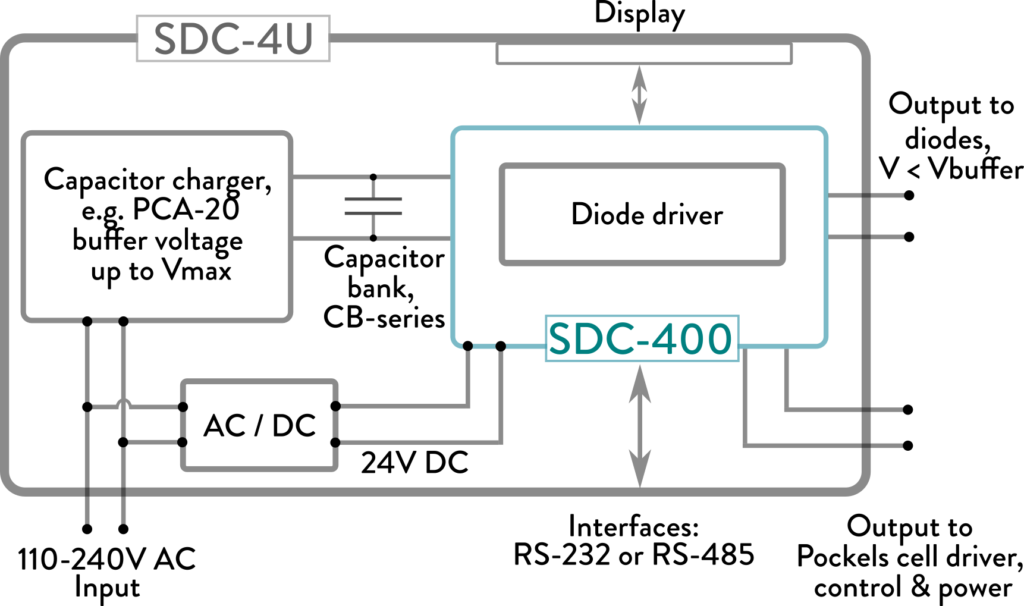
For a practical example of system integration, the accompanying diagram demonstrates how the laboratory-grade, 19-inch rack-mounted SDC-4U driver is successfully built around the core SDC-400 high-voltage module utilizing a forced-air cooling mechanism.
SDC-4U Driver Architecture Built Around the SDC-400:
Technical Specifications
| INPUT | |
|---|---|
| Power input | voltage source with the adjustable DC output voltage is recommended for most of applications. Output power must be matched with the required operating regimes. SDC-400 can control PCA-series capacitor chargers by OEM Tech or third-party sources of the input voltage |
| Maximum input voltage (Vmax) | 500 V for high-voltage version 100 V for low-voltage version Other on request |
| LV input | 24 V DC, 1A max |
| OUTPUT | |
| Regime of operation | pulsed |
| Maximum output voltage | nominal maximum output voltage is equal to the maximum input voltage Vmax, i.e.:
Actual output voltage applied to the diodes is several volts lower than the input voltage due to voltage drops across internal components and wiring. |
| Maximum output current (Imax) | 400 A, other on request |
| Output current | ~ 10-100 % of Imax adjustable, other on request |
| Pulse width | adjustable in 50 us – Tmax range, Tmax is 300 us by default, other on request |
| Maximum pulse repetition rate | 50 Hz for high-voltage version 500 Hz for low-voltage version other on request |
| Peak power | > 100 kW for high-voltage version 40 kW for low-voltage version other on request |
| Maximum average output power | 1500 W, other on request |
| Rise time | < 20-30 us typically, slow start adjustable in 0…50 us range |
| Bias current | +, model dependent (<50mA) |
| RECOMMENDED CABLES | |
| For diode connections | • inductance – < 500 nH • cross-section – 4 mm2 • length – < 50 cm (up to 2 m acceptable) |
| For external capacitor bank connections (high-voltage version) | • cross-section – 4 mm2 • length – < 50 cm |
| MISCELLANEOUS | |
| Protections/safety | • from overcurrent • from overheating • from incorrect input voltage • from too high frequency of synchronization pulses • door-interlock connection • quick discharge resistors connections |
| Cooling | two options are available: • forced-air cooling • water cooling |
| Interfaces | • RS-232 interface • RS-485 interface |
| Synchronizations | • 1 pc synchro input • 3 pcs synchro outputs |
| Pockels cell driver control | available |
| ENVIRONMENT | |
| Operating temperature | +10 … +40 °C |
| Storage temperature | -20 … +60 °C |
| Humidity | 0 … 90%, non-condensing |
| OTHER | |
| Size (WxDxH) | 150x256x142 mm for SDC-400-HV-A, for other see the User Manual |
| Weight | < 1.5 kg / < 3.5 kg for water and forced-air cooled versions respectively |
Options
Different customizations (e.g. non-standard output currents, non-standard diode voltages, software customizations, Pockels cell driver control) are possible on request.
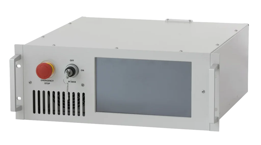
Rack-mounted 19-inch version of the SDC-400 with AC/DC power supply, capacitor bank, and graphical user interface (GUI) inside is available under the name SDC-4U
SDC-4U
How To Order
SDC-400-XX-Y, where:
- XX defines the voltage version of the driver, it can be either HV (high-voltage version of the driver) or LV (low-voltage version of the driver).
- Y code defines the cooling type, it can be either A (air-cooled version) or W (water-cooled version).
| EXAMPLES (SOME STANDARDIZED MODIFICATIONS) | |
|---|---|
| Model | Description |
| SDC-400-HV-A |
(*) – not at the same time, see also Modes of operations table below |
| SDC-400-LV-W |
|
Other modifications are available upon request.
Modes of operations
| PARAMETER | VALUE (*) | |||||
|---|---|---|---|---|---|---|
| SDC-400-HV | SDC-400-LV | |||||
| 300V mode | 350V mode | 400V mode | 450V mode | 500V mode | N/A | |
| Maximum input voltage (buffer voltage) Vmax, V |
300 | 350 | 400 | 450 | 500 | 100 |
| Maximum output voltage (**), V | < 300 | < 350 | < 400 | < 450 | < 500 | < 100 |
| Recommended external capacitor bank capacitance: | >15mF @ 300V | >15mF @ 350V | >15mF @ 400V | >8mF @ 450V | >5mF @ 500V | not required |
| Diode driver: | ||||||
| Max. output current, A | 400 | 350 | 300 | 250 | 225 | 400 |
| Recommended diode voltage, V (**) |
< 265 | < 320 | < 370 | < 420 | < 470 | < 65 |
| Pulse width (Tmin…Tmax), us | 50…300 | |||||
| Repetition rate, Hz | 0…50 | 0…500 | ||||
| Output limitations: | ||||||
| Energy limit | Imax*Vmax*Tmax | |||||
| Power limit, W | 1500 | |||||
| Guaranteed regime | 400A-265V- 250us-50Hz |
350A-320V- 250us-50Hz |
300A-370V- 250us-50Hz |
250A-420V- 250us-50Hz |
225A-470V- 250us-50Hz |
400A-65V- 250us-200Hz |
(*) Customizations (e.g. non-standard output currents, non-standard diode voltages and other parameters, software customizations, Pockels cell driver control customizations) are possible on request.
(**) Nominal maximum output voltage is equal to the maximum input voltage Vmax. Actual output voltage applied to the diodes is several volts lower than the input voltage due to voltage drops across internal components and wiring.