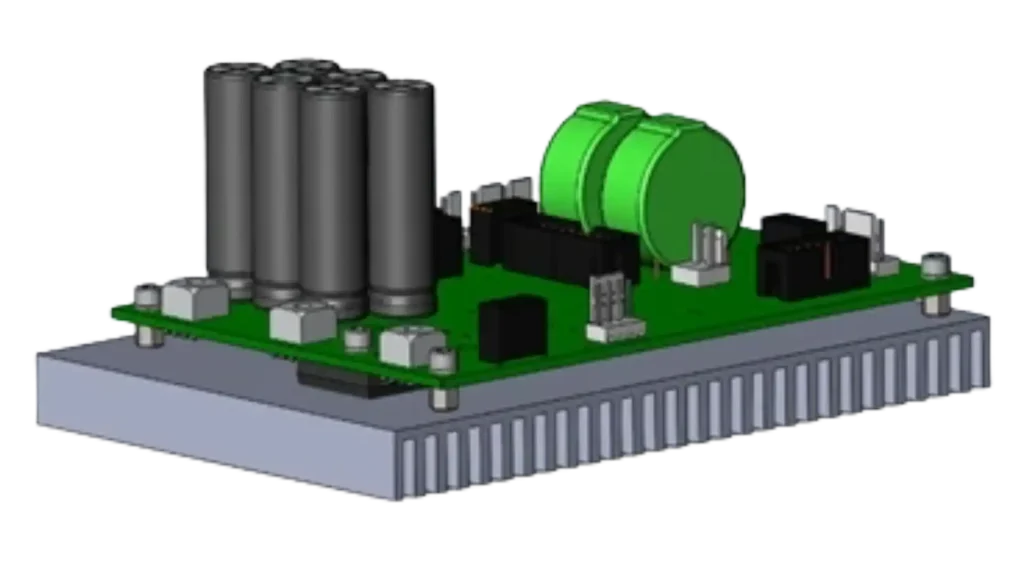
LDC-4 Pulsed Diode Driver
Product details
Downloads: Downloads
| File | Size | Updated |
|---|---|---|
| Software-VLC3-eng_V5_dec2018.pdf | 434 KB | December 23, 2025 |
| File | Size | Updated |
|---|---|---|
|
|
434 KB | December 23, 2025 |
Laser diode controller LDC-4 combines laser diode driver and two independent thermoelectric controllers (TEC). It is designed to provide pulsed and continuous modes of operation for laser diode modules used both independently and as sources of diode pumping for solid-state lasers (DPSSL) in the laboratory, medical and technological laser devices and systems. The power supply is controlled from a computer via VLC software.
Key Features:
| LDC | |
|---|---|
| Peak LDM current | up to 400 ANOTE 1 |
| Max bias current | 50 A |
| Max LDM voltage | up to 400 V NOTE 1 |
| LDM average power | ≤ 600 W |
| LDM working pulse length | 40 ÷ 100,000 µsec |
| Repetition rate | 0.1 Hz ÷ 10 kHz |
| Instability of the current amplitude | ≤ 1 % |
| Power supply of pilot laser | 5 V & 200 mA |
| TEC1 & TEC2 (Peltier Elements) | |
| Range of the temperature control | – 50 ÷ 120 °C |
| Discreteness of the temperature control | ± 0.01 °C |
| Max voltage | 22 V |
| Max current | 2 × 8 A |
| Additional Temperature Interlock TEC3 | – 50 ÷ 120°C |
| PHOTO-DETECTOR | |
| Linear range of the LDM photocurrent measurements | 0.01 ÷ 160 µA |
| Scale factor of light power/current conversion | 0 ÷ 100 W/µA |
| TRIGGER | |
| External triggering pulse amplitude Utrig_in (Impedance = 1 kΩ) | 5 V ± 20% |
| External triggering pulses duration | > 2 μsec |
| Output trigger pulse amplitude Utrig_out (Impedance ≥ 1 kΩ2) | 5 V ± 20% |
| Output trigger pulse duration | 5 μsec |
| Adjustable range of output trigger delay | 0 ÷ 3900 µsec |
| GENERAL | |
| Dimensions | 134 × 92 × 40 mm3 (see dimensional drw.) |
| Storage temperature | – 30 ÷ + 60°C |
| Operating temperature | + 5 ÷ + 45°C |
| Ambient humidity | < 98% |
| NOTE 1. Maximum values of LDM current and voltages depends on modification of the LDC-series board. For LDC-4-25V-100A maximum voltage and current are 25V and 100 A correspondingly. | |

LDC-4 can use 3 separate power supplies for:
If TEC 24 V power supply (J201, J202) is used, 12 V for PCB will be provided by onboard converter from 24 V. In this case connection of separate 12 V power supply (J1) is not necessary.


| Pin | Functionality |
| 1 | GND |
| 2 | +12 V (+24 V)* |
| 3 | NC |
*Can be chosen by onboard jumper resistors (R1 closed, R2 opened – 24 V, R1 open, R2 closed – 12 V).
Power LED shows, that PCB is switched on and indicates current mode of operation. Blinking red/green light correspond to normal operation LDC board. Continuous red light indicates that LDC is booted in programming mode.
Ready LED indicate that laser diode module (LDM) is ready to operate (continuous green light). If Ready LED is switched off LDM operation is blocked by some of the interlock.
| Pin | Functionality | ||
|
1 |
Power Green Anode |
3 |
Ready Anode |
|
2 |
Power Red Anode |
4 |
Ready Cathode |
| Pin | Functionality |
| 1 | GND |
| 2 | Lock1 |
| 3 | GND |
| 4 | Lock2 |
Controlled from software DC output. (12 V or 24 V, depending on PCB connection version).
| Pin | Functionality |
|
1 |
GND |
|
2 |
Controlled 12 V (24 V) output |
| Pin | Functionality |
| 1 | 12 V |
| 2 | Power GND |
| 3 | 24 V |
| 4 | Power GND |
| 5 | HV OK |
| 6 | Delay |
| 7 | DAC 1 |
| 8 | Pulse terminator |
| 9 | PhD1 Cathode |
| 10 | Ready LBC |
| 11 | 5 V |
| 12 | Signal GND |
| 13 | Trigger out |
| 14 | Trigger in (A) |
| 15 | Signal GND |
| 16 | Trigger in (C) |
| 17 | Clock |
| 18 | Data |
| 19 | Pilot- |
| 20 | Pilot+ |
|
Pin |
Functionality |
| 1 | NC |
| 2 | NC |
| 3 | TxD |
| 4 | NC |
| 5 | RxD |
| 6 | NC |
| 7 | NC |
| 8 | NC |
| 9 | GND |
| 10 | NC |
+24 V external power supply for Thermo-electric controllers (TEC). Through Internal PCB 24 V – 12 V converter also provides 12 V for PCB power supply.
| Pin | Functionality |
| 1 | +24 V |
Power GND pin of +24 V external power supply for Thermo-electric controllers. Through Internal PCB 24 V – 12 V converter also provides 12 V for PCB power supply.
| Pin | Functionality |
| 1 | Power GND |
GND Power pin of external LDM power supply.
| Pin | Functionality |
| 1 | Power GND |
Connects to LDM anode and to LDM power supply + pin simultaneously.
| Pin | Functionality |
| 1 | LDM Anode and +pin of LDM Power Supply |
Connects to LDM Cathode.
TEC Controller connectors. Provides connection of 3 external Thermo sensors (TS) and 2 outputs for external Peltier elements (TEC1 and TEC2). TEC1 and TEC 2 outputs are duplicated at J501 and J502 connectors correspondingly.
| Pin | Functionality |
| 1 | TEC1+ |
| 2 | TEC1- |
| 3 | TEC1+ |
| 4 | TEC1- |
| 5 | TEC1+ |
| 6 | TEC1- |
| 7 | GND |
| 8 | TS1 |
| 9 | TS3 |
| 10 | TS2 |
| 11 | TEC2- |
| 12 | TEC2+ |
| 13 | TEC2- |
| 14 | TEC2+ |
| 15 | TEC2- |
| 16 | TEC2+ |
TEC1 output (up to 22 V, controlled from software); it’s duplicated @J500 connectors, pins 1-6.
| Pin | Functionality |
| 1 | Peltier + |
| 2 | Peltier – |
TEC2 output (up to 22 V, controlled from software); it’s duplicated @J500 connectors, pins 11-16.
| Pin | Functionality |
| 1 | Peltier + |
| 2 | Peltier – |
OPERATING INSTRUCTIONS.
Connection of Laser Diode
The laser diodes must be connected to the LDC board using J303 (anode) and J304 (cathode) connectors by means of red (anode) and blue (cathode) wires of suitable length and cross-section.
The electrodes of the used LD should have short cut before connection and then the short cut must be removed.
Connection to the PC
Connect J8 connector of the LDC board with personal computer using serial or RS232-USB cable. In the last case install proper serial-to-USB converter driver on the PC.
Connection of the external power supply units (PSU)
Make sure that the PSU are off before connecting it to the LDC board.
LDC board can use 3 external PSU: PSU1 with 12 V DC output connected to J1 connector provides power supply for LDC logic circuits. Connection of PSU1 is unnecessary if PSU2 is used.
PSU2 with 24 V DC output connected to J201 (+) and J202(-) connectors provides power supply for LDC logic circuits and TEC outputs.
PSU3 connected to J302 (-) and J303(+) connectors provides power supply for laser diodes. Voltage of PSU3 is chosen according to the laser diode specification (+ 3-7 V above voltage drop across laser diode module). If necessary, ask tech support for the instructions to manage connection with your LD.
Switching the Diode Laser on
Switch on the Power supplies of LDC board. Power LED (J3 connector) on the front panel blinks with red and green light in working mode. Ready LED (J3 connector) indicating that laser operation is allowed by settings of all external interlocks.
Start VLC 3 software up and set desirable pulsed operating current, bias current, pumping pulse length (in us) and pulse pause (in ms) (see VLC Software Manual).
Set the desirable temperatures of TECs (Peltier) and check out dynamics of getting desirable LDs temperatures. If necessary one can adjust coefficients of PID regulators from the VLC3 window. Set proper mode and delay of triggering pulse for the used Q-switch.
Switch the laser on without triggering of Q-switch for the first time with arrow knob. Please be assured that used output voltage from AC/DC converter is quite sufficient to provide operation at maximum desirable current and repetition rates. If it is not so one can observe red lit at the down part of the working screen of VLC3 (look at figure below).
If necessary, adjust the voltage from Power Supply of your Laser diode till the moment when the lit turns green.
The shown signal indicates current status only in «PAUSE» and «START» modes. In «STATE» mode keeps the last indicated.
Vigitek, Inc. designs and supplies optical, electro-optical, and laser-related products and subsystems, and also supports OEM and custom developments for biomedical and industrial applications.
Our catalog includes engineering-grade components such as diode drivers, capacitor charging power supplies, controllers, and related electro-optical modules. Availability and configuration options vary by product.
Yes. We support OEM and custom configurations for many products. Share your target specifications (electrical output, pulse parameters, interfaces, packaging, and any test/documentation needs), and we’ll recommend the best-fit option and quote accordingly.
Yes. Send a short description of your application and key requirements (power, voltage/current range, pulse width and repetition rate, cooling constraints, interfaces, and intended use). We will help you select the most appropriate solution.
When applicable, we can provide user documentation and test information appropriate to the product and your requirements. If your program requires specific documentation or traceability, mention it when requesting a quote.
We can assist with integration questions, configuration guidance, and troubleshooting. For the fastest support, include your order/invoice number and product model/serial number (if applicable), plus a clear description of operating conditions.
Yes. We ship within the U.S. using common parcel carriers (UPS/FedEx) and LTL freight for larger items when needed. Shipping options and costs are provided with your quote or order confirmation.
Lead times depend on the item and configuration. Standard items generally ship within the lead time shown on your quote. Custom or build-to-order items may require additional manufacturing and test time.
Many Vigitek products are configured to match specific system requirements (electrical output, pulse parameters, interfaces, packaging, firmware, and test requirements). Publishing a single price can be misleading, so we provide quotes that match your exact application and quantity.
In most cases, we can provide a quote quickly once we have the key requirements (product/configuration, quantity, and ship-to location). For custom or highly specialized requests, we may ask a few technical questions to ensure accuracy.
Yes. Pricing often improves with higher quantities and ongoing production. Let us know your forecast and we’ll quote the most appropriate tier.
Often, yes. If a standard configuration meets your needs (or if certain options aren’t necessary), we’ll suggest a simpler, more cost-effective approach.
Custom and OEM developments are quoted based on scope, requirements, validation/testing, and deliverables. We’ll outline what’s included so you can compare options clearly.
Warranty and return eligibility vary by product and are confirmed on your quote or order confirmation. Returns generally require prior authorization. If you believe an item is defective or damaged in transit, contact us promptly with details and photos.
Vigitek, Inc. aims to ensure you receive products that meet specifications and perform as intended. Because many items are technical, configured, or built to order, returns are handled through a Return Authorization (RA) process.
Please contact us to request an RA before returning any item. Returns sent without prior authorization may be refused.
If a non-defective return is approved, the return window and shipping address will be provided with the RA. Items received outside the approved window may be refused.
After inspection/testing, we will determine the appropriate outcome based on the issue and the terms of your purchase, which may include repair, replacement, credit, or refund (as applicable). If no fault is found or the issue is outside warranty/return eligibility, evaluation fees and return shipping may apply.
If you are unsure whether an item qualifies for return, contact us before shipping anything back.
Vigitek, Inc. provides a limited warranty on select products we manufacture and sell (for example: diode drivers, capacitor charging power supplies, and controllers). Warranty coverage and duration may vary by product and will be confirmed on your quote, order confirmation, or invoice. For custom/OEM developments or engineering services, warranty terms are governed by the applicable project agreement.
This limited warranty covers defects in materials and workmanship under normal use and service, when the product is installed, operated, and maintained according to Vigitek documentation or written instructions. Warranty coverage begins on the date of shipment or delivery (unless otherwise stated in writing).
Please contact us to obtain a Return Authorization (RA) before sending any product/part back for evaluation.
Include your order/invoice number, product model and serial number (if applicable), a clear description of the issue, operating conditions, and photos/video when possible. We may ask you to perform basic troubleshooting steps to speed up resolution.
If the issue is determined to be a covered warranty claim, Vigitek will, at our option:
Repaired or replaced items are covered for the remainder of the original warranty period, unless otherwise required by law.
Products returned for evaluation must be packaged appropriately to prevent transit damage and must display the RA information as instructed. Items returned without prior authorization may be refused. Transit damage is not covered by this warranty.
Except as expressly stated above, this warranty is provided in lieu of all other warranties, express or implied, including (to the extent permitted by law) implied warranties of merchantability and fitness for a particular purpose. Some jurisdictions do not allow certain limitations, so parts of this policy may not apply to you.

Vigitek, Inc. ships within the United States. Shipping options, lead time, and costs depend on the product type, quantity, destination, and any handling requirements.
For shipping questions or special handling requests, contact us:
Many of our products are engineering-grade components (drivers, power supplies, controllers, and electro-optical modules) that are often configured to match a customer’s exact system requirements. Because specs, compliance needs, test requirements, and quantities can vary significantly, a single “list price” rarely reflects the best or most accurate cost for your application.
Tell us what you’re building and we’ll recommend the best-fit solution and provide a detailed quote.
LDC-4 Pulsed Diode Driver