
Custom Power Supplies
Product details
Available for order
Close to 80% of our flashlamp drivers are built in accordance with custom specifications of each end-user. This work can be done with NO NRE CHARGES even for SMALL QUANTITY!
Available for order
Reply within 1 business day
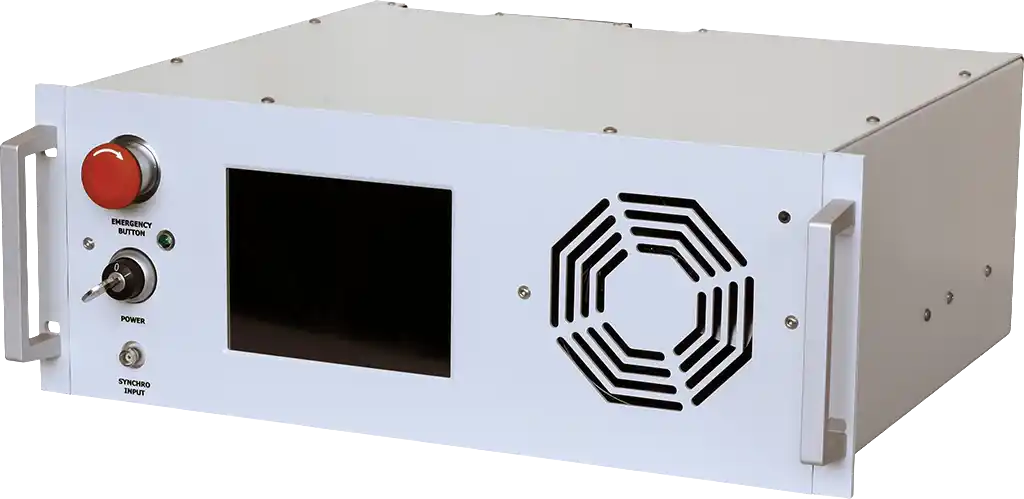
Example I: FLD-5U Dual-Channel Flashlamp Driver
- Dual channel flashlamp driver with the following characteristics:
- Pulsed output
- Two channels operating independently; up to 3,000W per channel
- IGBT-based switch, variable pulsewidth
- Max. Voltage – 900 V
- Touch panel LCD graphic user interface
- Input – 230 VAC
- Dimensions: 19” rack width, ~400 mm depth, 5U height (~220 mm).
FRONT PANEL DESCRIPTION
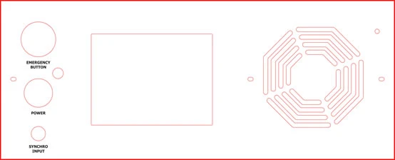
| EMERGENCY BUTTON | stops operations when pressed must be released to allow the operations |
| POWER | switches module on and off must be turned to the right to allow operations |
| SYNCHRO INPUT | controls the module in external synchronization mode |
FIRMWARE DESCRIPTION
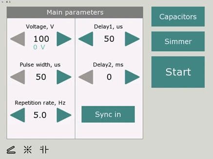
| VOLTAGE | Sets the desired output voltage; cyan number below indicates the real voltage capacitor bank is charged to |
| PULSE WIDTH | Sets the desired pulse width |
| REPETITION RATE | Sets the desired repetition rate (in internal synchronization mode only) |
| DELAY 1 | Adjustable delay of the first synchro-output |
| DELAY 2 | Adjustable delay of the second synchro-output |
| SYNC IN | Switches the module between internal synchronization mode and external synchronization mode In internal synchronization mode flashes are defined with the internal timer In external synchronization mode (SYNC IN is pressed) flashes are defined with the external TTL signal applied to the SYNCHRO INPUT connector |
| CAPACITORS | Starts / stops capacitor charging module After CAPACITORS button is pressed capacitor charging module tries to charge internal capacitor battery up to value selected within VOLTAGE group The third pictogram in the status bar indicates if capacitors are successfully charged or not; normally it takes several seconds to charge capacitor battery from zero to Vmax and much less within interpulse interval |
| SIMMER | Starts / stops simmer supply module After SIMMER button is pressed, simmer supply continuously tries to strike flashlamp and establish the simmer discharge The second pictogram in the status bar indicates if the simmer discharge is successfully established or not; normally it takes a few seconds to establish the simmer discharge |
| START / STOP | Output of the module is disabled till START button is pressed Note: before pressing START button you need to establish simmer discharge, turn on the capacitor charging module and short-circuit all the interlock circuits |
STATUS BAR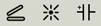 |
Status bar contains three pictograms depicting correspondingly:
|
BACK PANEL DESCRIPTION
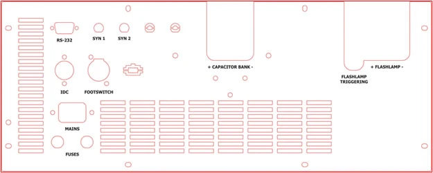
| MAINS | Connects module to the mains (230VAC, 50/60Hz) |
| FUSES | 2x fuses (16A rating) |
| IDC / FOOTSWITCH | 2x interlock door connectors both connectors must be short-‐circuited to allow the operations |
| RS-232 | Allows to control module via rs-232 interface |
| SYN 1 | Synchro-output, delayed up to 300us |
| SYN 2 | Synchro-output, delayed up to 300ms |
| FLASHLAMP «+» FLASHLAMP «–» |
Flashlamp connections |
| FLASHLAMP TRIGGERING | [NOT USED IN THIS MODULE] |
| CAPACITOR BANK «+» CAPACITOR BANK «–» |
To the external capacitor bank / banks |
RS-232 COMMAND DESCRIPTION
Module is supplied with RS-232 user interface. D-SUB 9-pin connector is located at the back side of the module. Characteristics of RS-232 interface are given below.
RS-232 connection parameters: 38400 bps, 8 data bit, 1 stop bit, no parity Command format is: {command} {data (optionally)} {end-of-line}
- Command is 1 character long (see list below)
- Data is ASCII‐string, command and data must be separated with space (space symbol)
- End-of-line symbols are \n or \r\n
List of available commands:
- v – sets the desired output voltage (in volts, example «v 300»)
- p – sets the desired pulse width (in us, example «p 1000»)
- f – sets the desired pulse repetition rate (in hz, example «f 5»)
- u – sets the synchronization mode («u 0» – internal , «u 1» – external)
- t – external synchronization edge («t 0» – rising edge, «t 1» – falling edge)
- d – delay 1 (in us, example «d 100»)
- h – delay 2 (in ms, example «h 100»)
- V, P, F, U, T, D, H – returns the corresponding value set point
- s – turns the simmer supply on and off («s 1» – on, «s 0» – off)
- c – turns the capacitor charging module on and off («c 1» – on, «c 0» – off)
- r – enables / disables the output («r 1» – enables)
- S, C, R – returns the corresponding value set point
- mV – voltage monitor
- mF – returns fault state
- mR – returns ready state (status of the capacitor charging module)
- mI – returns IDC state
- mS – returns simmer sensor state
| Parameter | Minimum | Maximum | Increment |
| output voltage, V | 100 | 800 | 1 |
| pulse width, us | 50 | 300 | 1 |
| rep. rate, Hz | 1 | 10 | 1 |
| delay 1, us | 0 | 300 | 1 |
| delay 2, ms | 0 | 300 | 1 |
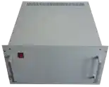
Example II: FLD-6U Dual-Channel Flashlamp Driver
ELECTRICAL SPEC
| Input | |
|---|---|
| Input Voltage | 1 phase, 230VAC (-20%/+10%), 50/60 Hz Max. current 8A |
| Type: | Multichannel; 4 independent channels |
| Output (for each channel) | |
| Discharge type | complete discharge |
| Capacitor battery | 360 µF |
| Max. voltage (Vmax) | 2000 V |
| Voltage Accuracy & Stability | 2% Vmax |
| Rated flashlamp | Ko – 19.7 Ohm A1/2; arc length – 200 mm |
| Pulse width (with rated flashlamp) | 300-350 µsec |
| Max. repetition rate (at max. output voltage) | 0.2 Hz |
| Max. output power | 150 W |
| Triggering | External triggering; module doesn’t contain any triggering circuits; it just waits while external triggering occurs |
| Simmer current | 600 mA |
| Simmer current stability | 5% |
| Interface | RS-485 |
| Hardware Protections | from overvoltage, from overheating, from flashlamp breakdown, 10 A fuse |
| Environment | |
| Operation temperature | 0…+40oC |
| Storage temperature | -20…+60oC |
| Humidity | 90%, non-condensing |
| MECHANICAL SPECIFICATION | |
| Size (LxWxH) | 481x474x264 mm |
| Weight | 15 kg |
FRONT PANEL DESCRIPTION
Front panel consist of just a few elements:
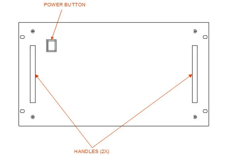
POWER switch – turns power supply on and off
HANDLES – two handles
BACK PANEL DESCRIPTION
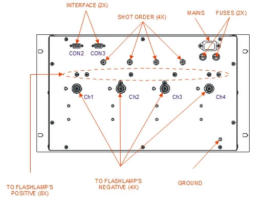
- MAINS – standard computer power socket; should be used to connect module to the mains
- FUSES – two 10A fuses
- GROUND – M6 threaded stud; should be used for module’s grounding
- FLASHLAMP POSITIVE – eight screws (two for each channel; one or two screws in each channel may be used for connections); flashlamp anodes should be connected to these screws
- FLASHLAMP NEGATIVE – four high voltage connectors (manufacturer Fisher Connectors; type High-Voltage Receptacle D 105 A049; ordering code FP01.684/104186); flashlamp cathodes should be connected to these connectors
- SHOT ORDER – four BNC-type connectors; synchronization pulse applied to some
- SHOT ORDER connector causes high voltage pulse in the corresponding channel
- INTERFACE – two D-sub type connectors; are used to connect modules to each other and to the control unit; CON2 connector, the right one is CON3 connector
Channels are aligned from the left to the right. First channel is the left one, fourth channel is the right one.
Products in this series: