- High-Voltage Amplitude ………………………………………………………….. 2000 ÷ 6000 V
- HV Pulse-to-Pulse Instability …………………………………………………… 5%
- Max Impulse Current ……………………………………………………………….. 30 A
- Max Capacitance ……………………………………………………………………… 100 pF
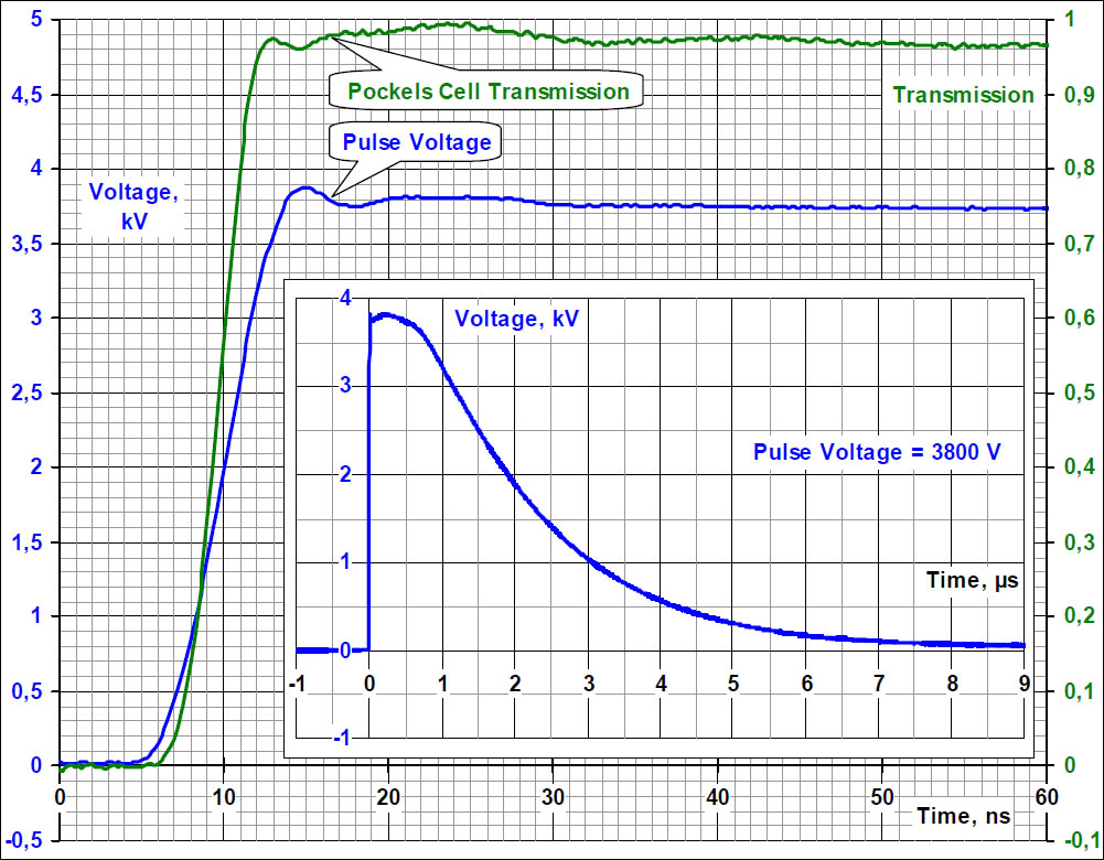
- Rising Front Duration ……………………………………………………………….. 3 ÷ 8 nsec
- HV Pulsewidth (factory-set) ……………………………………………………… 0.2 ÷ 2 μsec
- Falling Front Duration ………………………………………………………………. 0.2 ÷ 0.5 μsec
- Max Repetition Rate (Frequency) ……………………………………………… 20 kHz
- HV Pulse delay Vs. TTL trigger pulse ………………………………………… 60 nsec
- TTL Signal Amplitude ……………………………………………………………….. 3 ÷ 15 V
- Input DC Voltage ………………………………………………………………………..5 ÷ 15 V
- Current …………………………………………………………………………………….. 150 mA
- Mounting Holes (∅ 3.3 mm) ……………………………………………………. 44 × 74 mm
- Dimensions ………………………………………………………………………………. 50 × 80 × 24 mm3
- Working Temperature Range ………………………………………………….. –40 ÷ +60°C
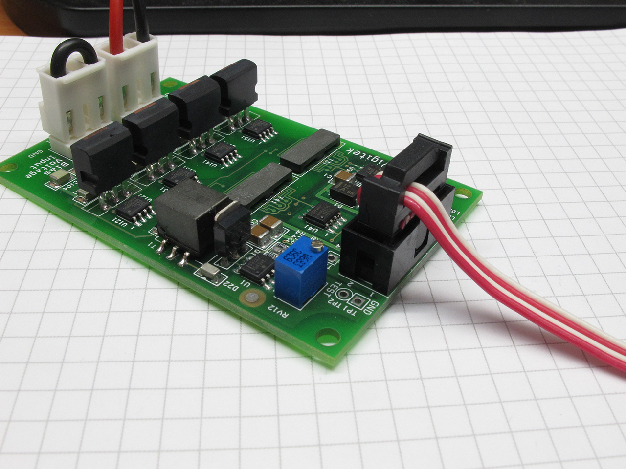
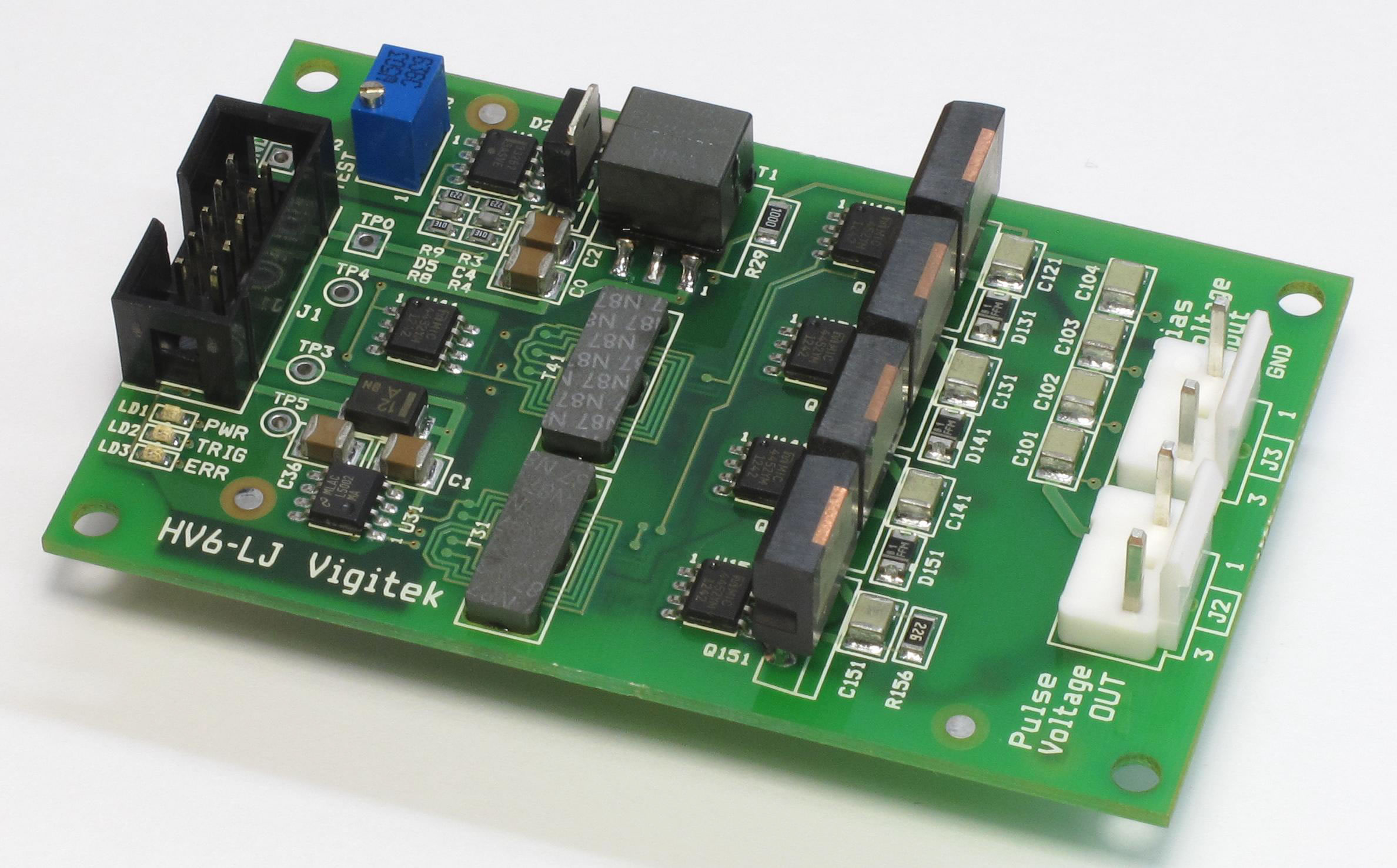
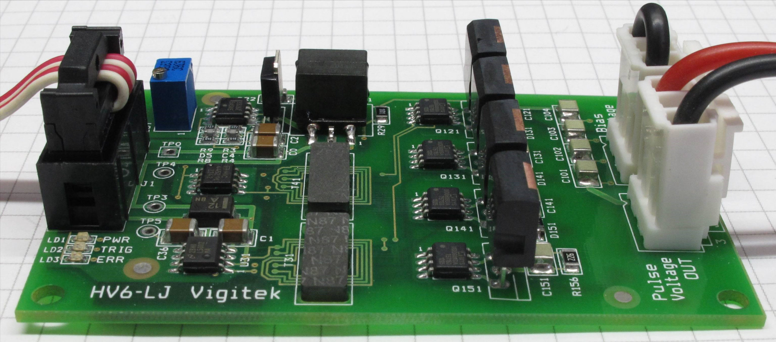
LAYOUT OF MAIN CONNECTORS AND ELECTRONIC COMPONENTS
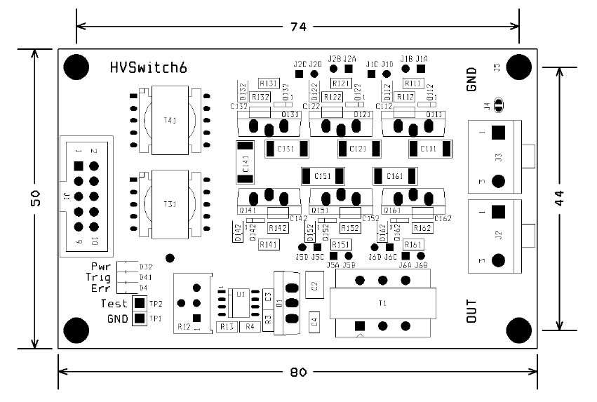
Input Connector J1, type IDC-10 (2.54mm):
1 – Input Trigger Pulse
2 G– ND
3 – DC Voltage
4 G– ND
5 – «Error» Message Signal
6 G– ND
7 – HV Amplitude Control 1:10000, or HV setting
VOUT = 1000 × (6 – V7)
8 G– ND
9 – Not/Connected
10 – GND
In order to set HV Amplitude remotely using Pin 7 of J1 Connector, it is necessary to move potentiometer R12 to the extreme right position, соresponding to the highest voltage. Input Resistance (Impedance) of Pin 7 is 4.8 kOhm.
Output Connector J2 type PW-03M (3.96mm):
1 – «negative» Q-switch electrode;
3 – «positive» Q-switch electrode.
Input Connector J3 type PW-03M (3.96mm):
1 G– ND
3 – «Plus» DC-bias Voltage applied to the Q-switch
HV Amplitude Control – R12.
TP1 – GND
TP2 – High-Voltage Adjustment 1:10000
LED Indicators:
D32 (Green) – «Pwr» – DC Voltage detected;
D41 (Yellow) – «Trig» – Input Trigger Signal;
D4 (Red) – «Err» – No High-Voltage Output;
ELECTRIC BLOCK-DIAGRAM
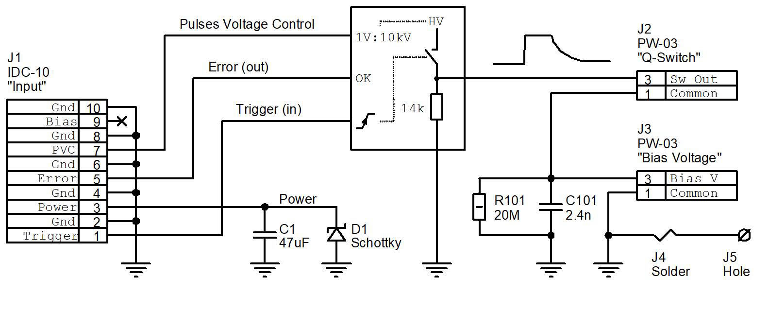
Schematic for the fast rising and falling fronts
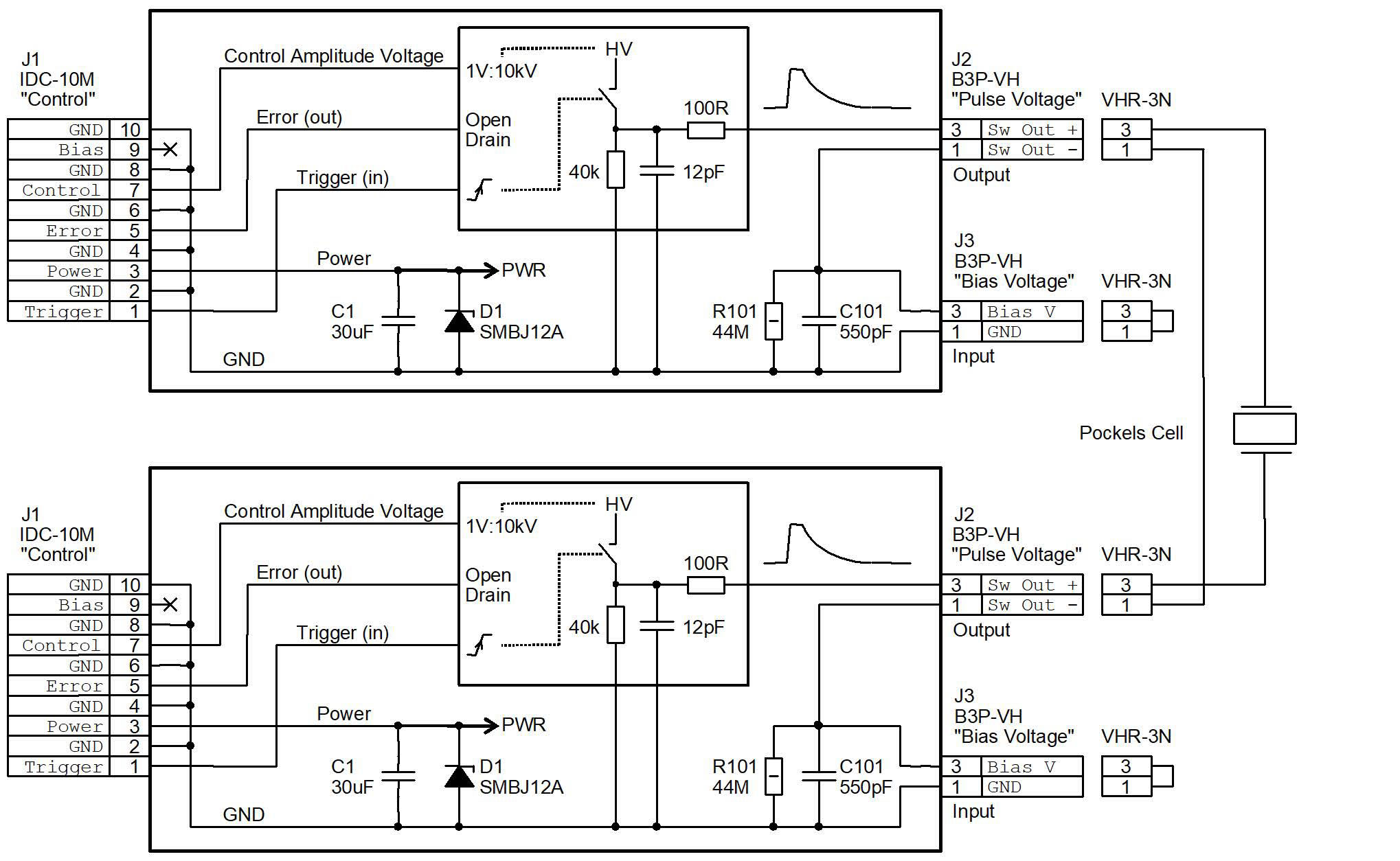
Switching waveforms
